|
< Back to the Projects
Previously, on Dragon Ball Z Bad64's Workshop...

Wait. That's not where we left off !
Alright, alright. I did build a couple things off camera, but really y'all haven't missed much. Let me give you a recap:
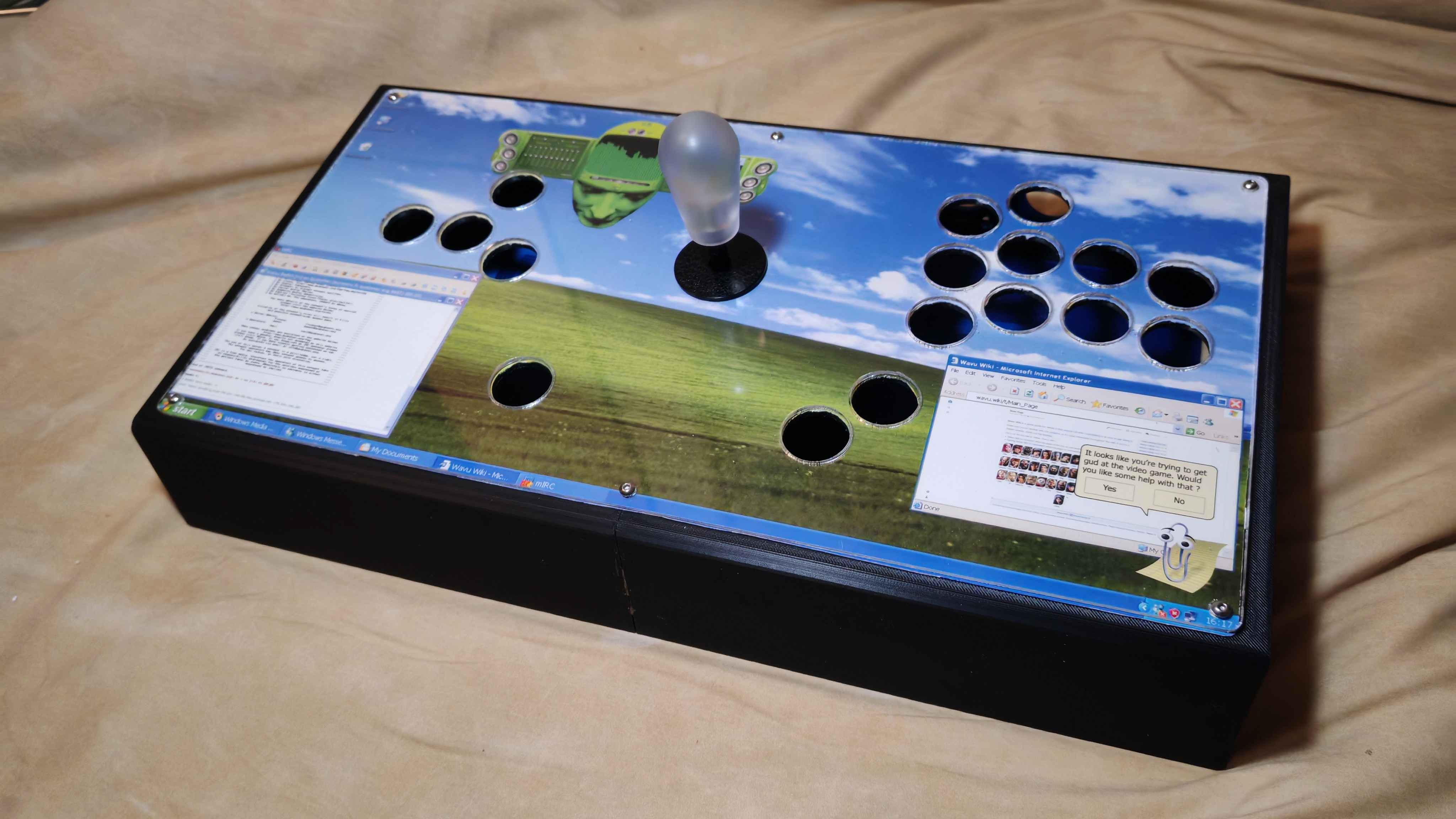
- As mentioned in the previous part, I did mount the lever, a Knee v1. Due to, uh, more than questionable artwork choices, I elected to replace the (otherwise gorgeous) translucent red ROX Knee bat top with a more neutral frosted translucent one.
- Of course the most obvious point is the artwork. It's really nothing special to put in place, though one could argue the printing and cutting stages are worth documenting (because yes I cut this thing by hand). Really it's just cutting paper though.
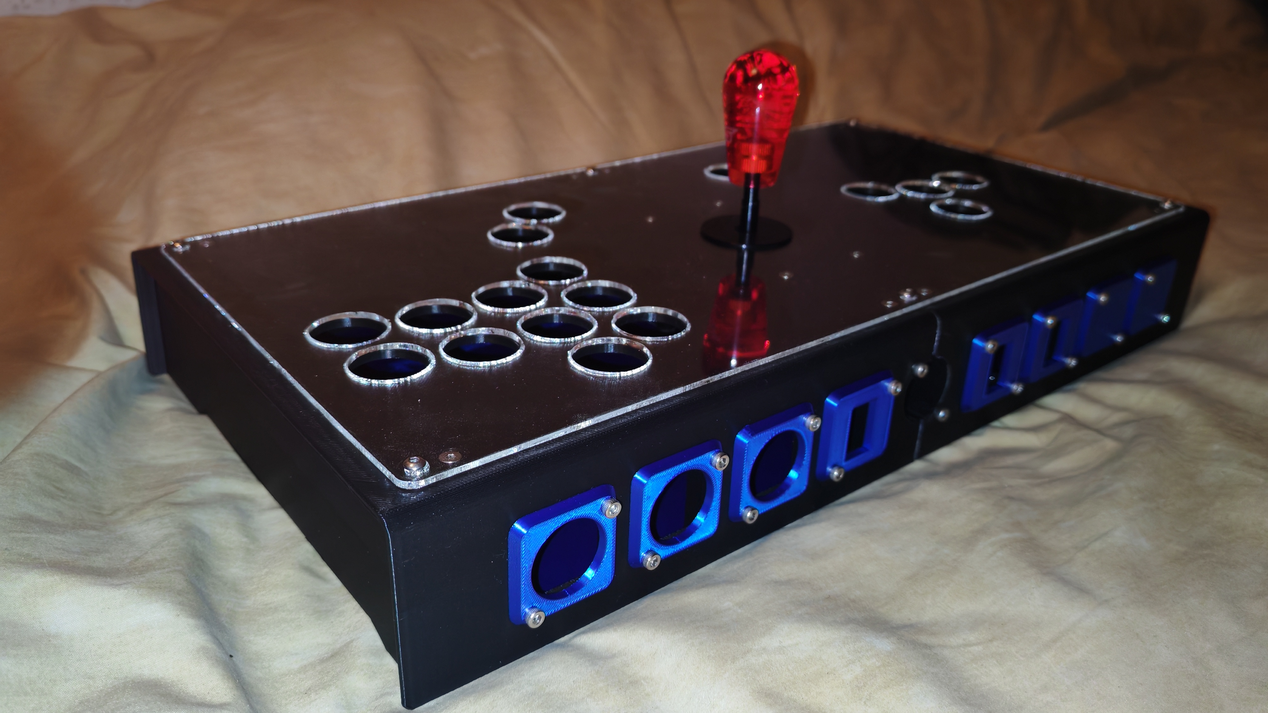
- And the one not visible in this image: I printed and mounted the option plates to the front facing side of the stick. More on that in a minute.
This is where we actually left off... sorta
The connoisseurs among you might have spotted a few things that, for all intents and purposes, don't really belong on a fight stick. Namely, those toggle switch mountings. What I haven't mentioned yet is that a lot of the redundant stuff on this build is toggleable using the aforementioned switches, in order to still keep it tournament legal.
You see, big tourneys like EVO have some rules regarding what a controller can and cannot do in terms of inputs. Namely, they explicitly disallow having an given input tied to more than one physical button (and the opposite, they also rule out one button doing multiple inputs - at least on the hardware side. "Macros" are allowed if they can be done from the in-game button config menu like 1+2 or PPP), which in turn means my 20-buttoned monstrosity needs something to be done to become compliant with the rules. We'll get back to that in a minute; first, let me mount the buttons to the panel. I'm not gonna document the whole process, I assume most of you know how to screw buttons onto a flat surface. These are Crown SDB-202 buttons, in 24mm, that I will eventually mod with extra clicky Kailh Speed Bronze switches:
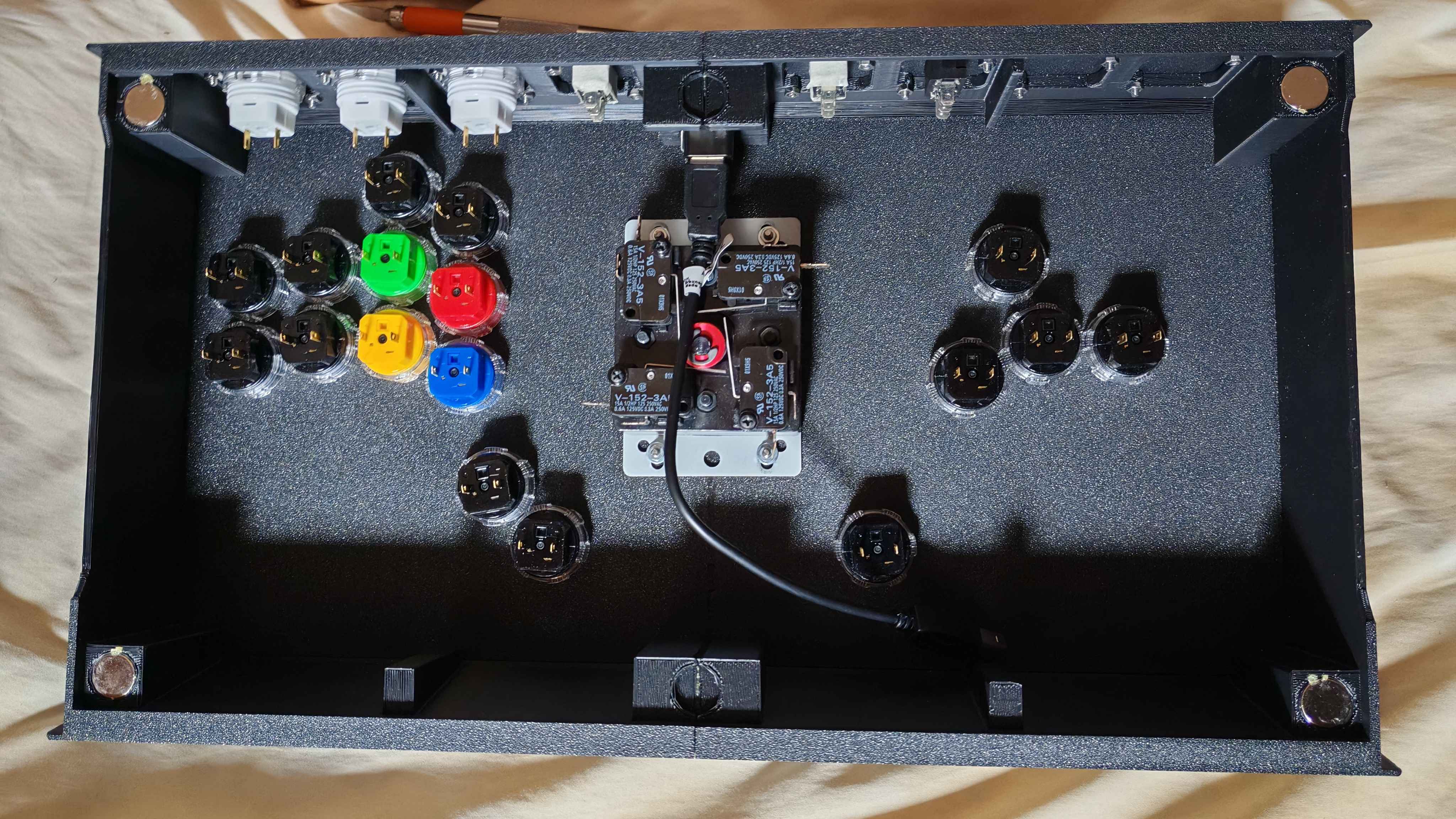
For the record, I rotated all of them 90° clockwise (from this POV) to try and make the ground chain a little cleaner. (Don't pay attention to the cable, I replaced it with an angled extension)
The key to success
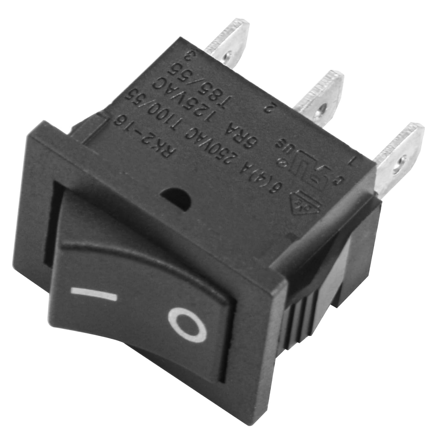
This fella above is a switch. You've probably seen a few of them in your lifetime. They turn a lot of stuff on and off in our modern landscape.
This specific one is a SPST switch, which stands for Single Pole, Single Throw.
Single pole refers to the number of circuits that particular switch can control at once, which in this case is only one.
Single throw is the number of positions the switch can hold. For reasons I'm not entirely clear with, this is actually the number in question minus one, so a single throw switch holds two positions (on and off), a double throw holds three (usually on, off, and on) and so forth.
This particular switch is called a On-On switch; the center pin is common to both circuits, and the rocker can close one or the other. Leading to a (genuinely very sensible and logical) question I've been asked a few times:

Why didn't you use a DPDT On-On-On switch ? Wouldn't that allow you to enable all inputs at once ?
Well to put it simply, it's because of overzealotry regarding the rules. Such a DPDT switch is nice and convenient for sure, but they also give me the possibility of accidentally infringing the rules (let's say if I were to not notice that a given switch is on its central position, enabling both inputs tied to it). With a SPST on-on, I can guarantee this cannot happen, thus making it less of a headache for both me and tournament organizers to ensure rules compliance.
Let's go back to our SPST switch. I've mounted three of them: One allows me to toggle which button is the Up cardinal in leverless mode, one toggles between leverless and lever, and the last one toggles between the two L3/R3 clusters. I hope y'all like badly cropped KiCAD screenshots, here's switch numero uno: the Up cardinal.
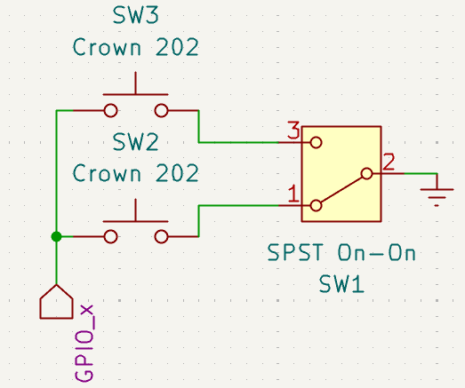
Note: I used a DPDT symbol for ease of understanding, but this is a SPST On-On switch
(I also don't remember which GPIO it's actually tied to, but that doesn't really matter)
That's the theory at least. If you're unsure of what that diagram means, I'll break it down for you.
First, we have a signal wire coming from GPIO_x (on the board it's the screw terminal labeled "UP" here; note that I could have used the corresponding 2x10 header as well). In practice I chose to put two wires in this terminal, one going to SW2 and one going to SW3 (both of them are just Crown SDB-202 buttons and are largely interchangeable). As long as the connection is solid it doesn't really matter how one closes a circuit.
So those wires go into their respective button on one end, and come out the other on what would normally be their path to ground. Ground is a little bit hard for me to vulgarize, so please just trust me on that one. The point being that when you press a button, you bridge the internal contacts, closing a circuit between the GPIO pin and ground, which as far as the board is concerned pulls that particular pin to zero volts, thus triggering what's called an edge transition and therefore a signal. (Why exactly the board registers a low voltage as a press isn't relevant and you can probably find someone way better than me to explain it on Youtube)
Those ground wires then enter THE SWITCH on poles 1 and 3. 2 is the common pin, as I've explained above. So depending on the position of the switch, either pole 1 or pole 3 are connected to ground, and therefore able to complete the circuit, thus triggering an input.
If you're curious (and you damn well should be), using one of the aforementioned DPDT On-On-On switches, the "middle" position bridges both contacts to the central set of pins (since it's double pole, y'know). This requires slightly different wiring, but the principle is the same, and indeed it would enable both inputs at the same time.
Onwards to switch 2: Lever/Leverless !
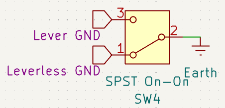
Lot simpler on paper
That one should be easier to understand if you've read all my yapping above. Basically: grounds in, ground out. The leverless cluster has its signal wires connected to the screw terminals, and the lever is wired to the 2x10 pin header. There is no real reason for that and I could have grouped the inputs, but this is going to make troubleshooting easier for me down the line, as well as making swapping the lever easier too. (Not that I intend to but the call of the full collar is always strong)
Last switch: L3/R3 !
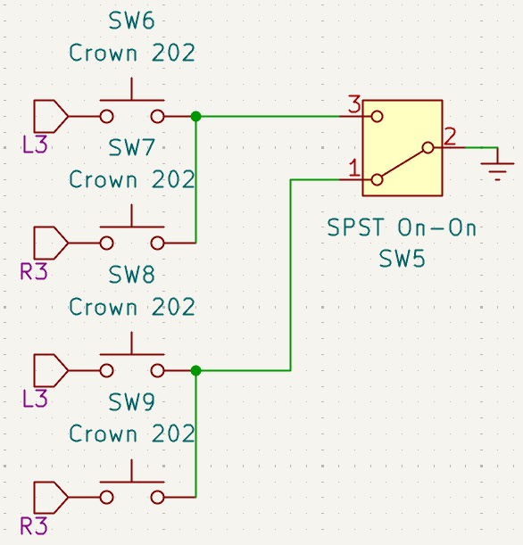
Same but with more stuff
Pretty much the combination of both previous switches: we have multiple daisy-chained inputs (L3 and R3), two buttons grounded together two by two, and a switch to toggle which one can actually complete its path to ground to create an input. It might look a bit daunting but really, it's nothing truly complicated.
But that, of course, is merely the theory. Now let us observe how the practice side went.
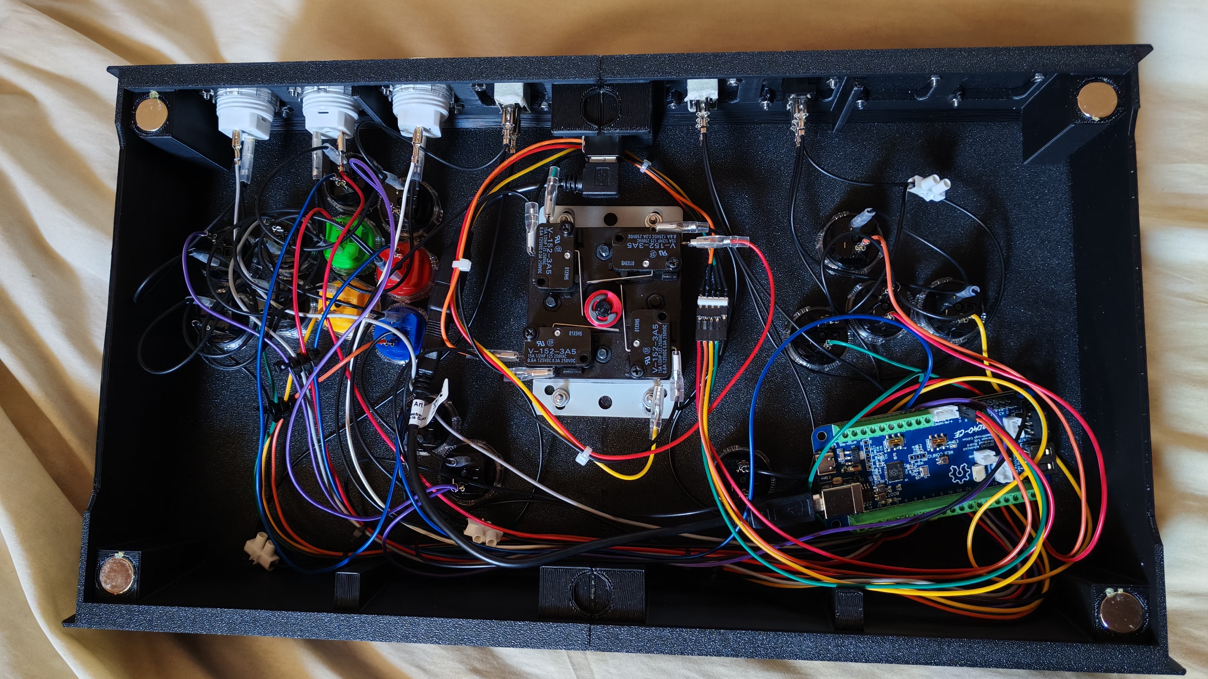
WHAT THE FUCK
In case that picture didn't sell it, I am not very good at cable management. An attempt was made using zip ties as impromptu cable combs, and also crimping a custom Dupont harness for the lever:
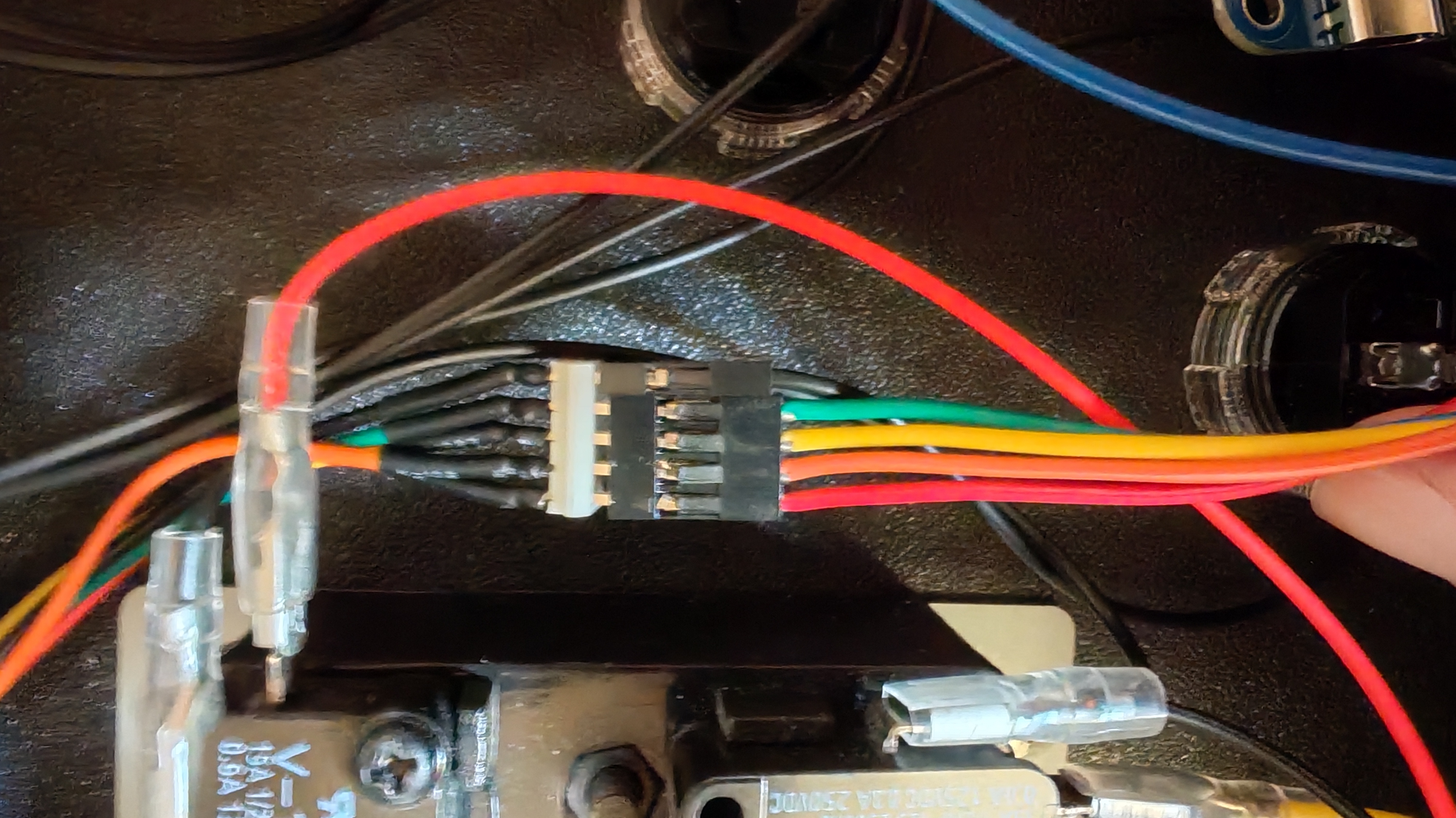
Y'know what, it holds. Good enuff.
Remember the L3/R3 wiring hulabaloo ? Here's a closer look at how I set that up on the signal side. I've highlighted the wires (pink for L3 and blue for L3) to make them slightly easier to follow. As you can see, I've done pretty much exactly as the schematic above, daisy-chained the inputs together, and let the ground switch sort out which ones count as active inputs.
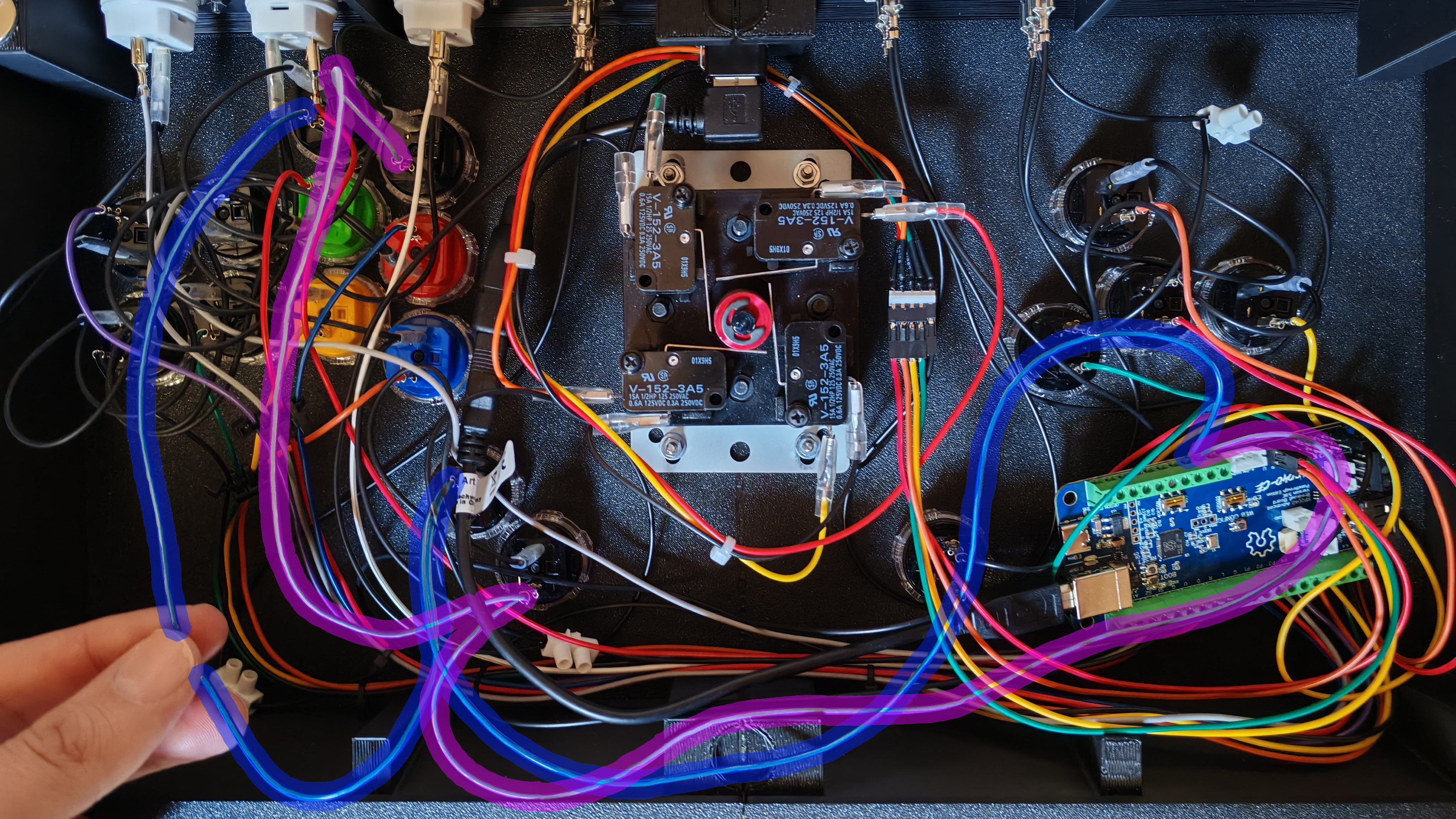
Don't worry, I moved the wires before closing it
Everything from this point on is very much normal fight stick things, you chain the grounds together for the various inputs (including those that have been switched up), connect to the board, do the signal wires, and eventually you end up with this:
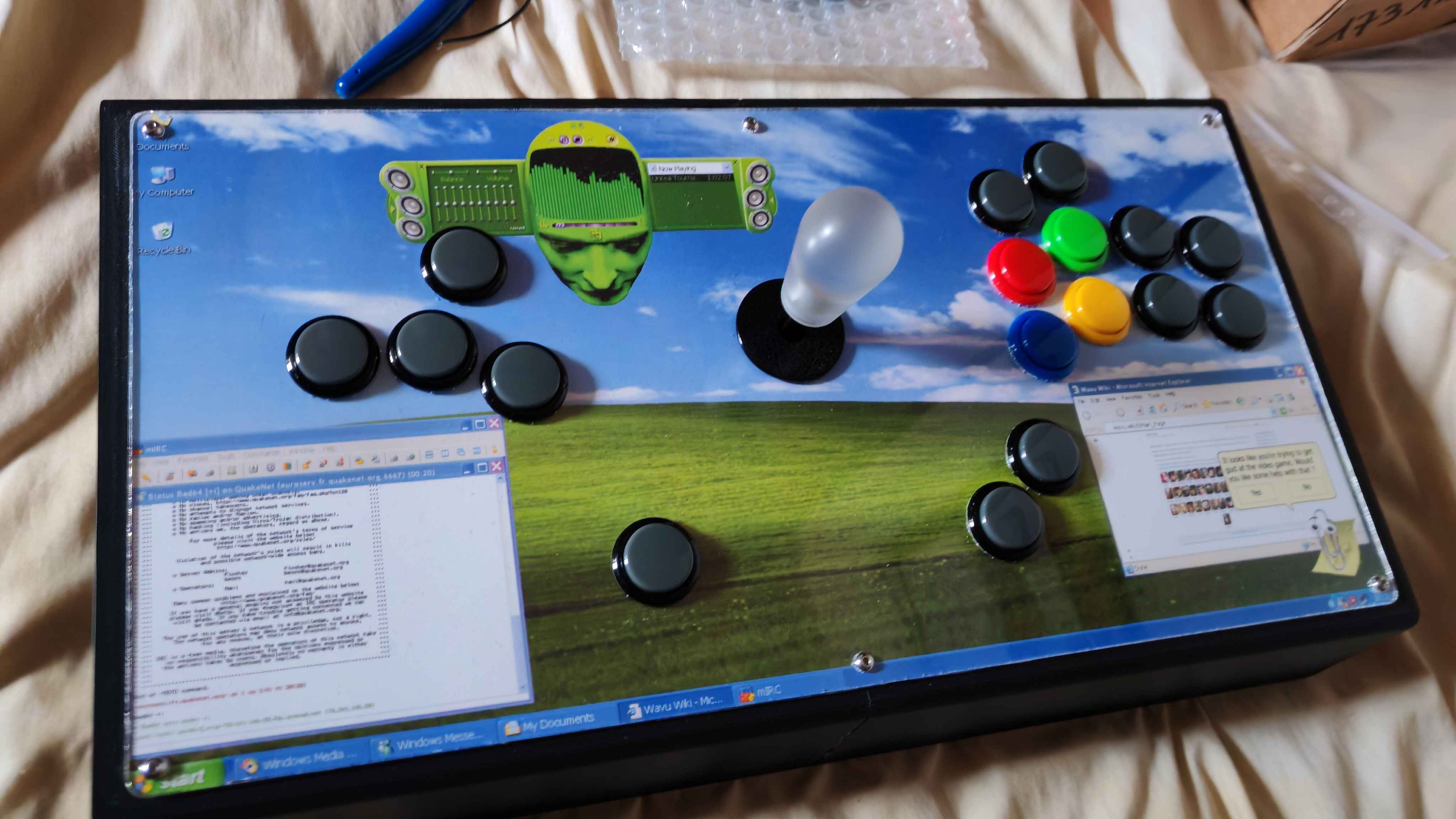
Bask in the Bliss dot jaypeg
With everything working as intended, I'm now ready to go back to training (just in time for Season 3 of Tekken, yay) and eventually to build something else next time ! Perhaps I'll also add a Nunchuk port to this one...
Either way, that's it for this build log. Hope y'all enjoyed it !
- Bad64
|